Seismic activity monitoring using distributed acoustic sensing
In this study, distributed acoustic sensing technology was used to monitor seismic activity south west of Japan. A distributed acoustic sensing device was connected to a 50km-long fibre optic cable, offshore Cape Muroto. The majority of the fibre optic cable rests due to its own weight on the ocean floor.
The distributed acoustic sensing device was designed and developed by the research team at the University of Southampton. The system has a 5 m spatial resolution and a spatial channel separation of 33 cm (300 MSa/s). The device was sampling strain disturbances on the fibre optic cable with a rate of 500 Hz throughout the whole span of the fibre optic cable (50km). A photo of the distributed acoustic sensing is shown in Figure 1.

Figure 1. Photo of the distributed acoustic sensing device. The device was designed and developed at the University of Southampton and was used to collect strain data for this research study.
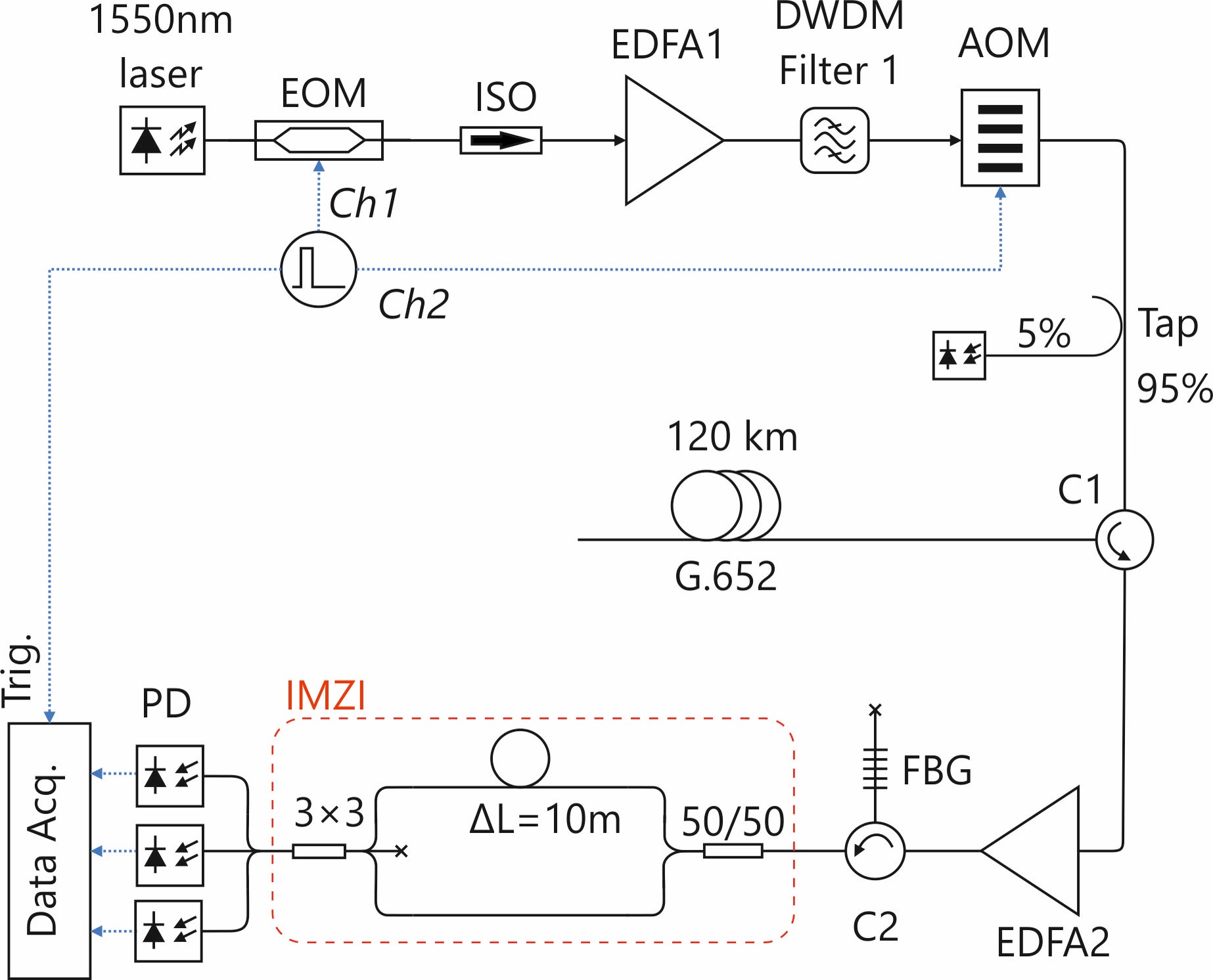
Figure 2, shows the block diagram of this device. In this arrangement, a narrow linewidth DFB laser diode (λ =1550 nm, Δν = 40 kHz) was used as a seed laser. The laser was externally modulated by an electro-optic modulator (EOM) to generate 50ns probe pulses with a repetition period of 2ms. The probe pulse was then amplified by an Erbium-doped Fibre Amplifier (EDFA) to reach 220 mW peak power. To eliminate the forward Amplified Spontaneous Emission (ASE), a dense wavelength division multiplexing (DWDM) filter with 100GHz bandwidth and an acousto-optic modulator (AOM) with an extinction ratio of 50dB were used. A 95/5 tap coupler was added at the output of the AOM to monitor the probe pulse.
The probe pulse was launched into the sensing fibre via a circulator which is also used to collect the backscattered light. The backscattered Rayleigh light from the sensing fibre was amplified by an optical amplifier (EDFA2) and filtered by a narrow FBG filter (λB= 1550.1 nm, Δλ = 5 GHz, Reflectivity = 70%) to remove the ASE. The amplified backscattered Rayleigh signal was then passed through an IMZI with a 10 m path imbalance and the intensity of the mixed signal at the output of the interferometer was measured by three amplified photodetectors (BW = 600 MHz, TIA = 40 kW). The detectors were sampled with a 300 MHz bandwidth PCIe digitizer at a rate of 330 MSa/s.

Figure 2. Block diagram showing the working principle of the distributed acoustic sensing device.
